Design Specs - English
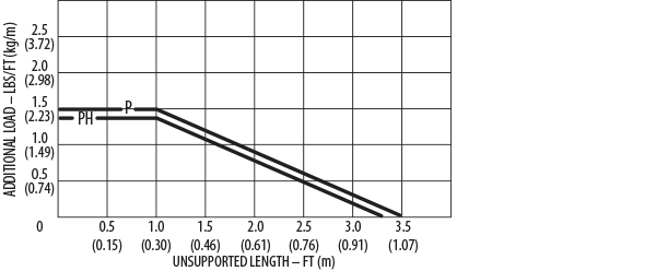
Weight Load Chart
How To Create A Part Number
P Series:
Model – Height – Length – Bracket (fixed) – Bracket (moving)**
Example: P1-5-36.00-#2OUT-#2IN
PH Series:
Model – Height – Hinged Bar Location* – Length – Bracket (fixed) – Bracket (moving)**
Example: PH2-4-INNER-40.50-#4IN-#4 IN
⇒ Length is specified in inches, to two decimals. It is the distance between flanges
⇒ (see formula on carrier side view diagram)
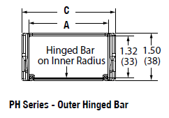
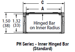
*Only on PH Series: Hinged bars are available on inner or outer radius. Hinged bars on inside radius is standard. Please specify when ordering.
**Specify bracket flange: inward (IN) or outward (OUT).
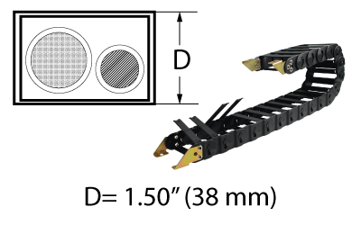
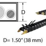
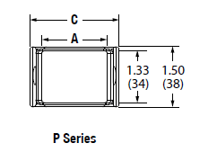
Carrier Cross Sectional View
| Model |
A (inside width) |
C (outer width) |
Weight (lb/ft) |
| P1 |
1.25 |
1.72 |
0.35 |
| PH1* |
1.25 |
1.72 |
0.35 |
| P2 |
2.50 |
2.97 |
0.41 |
| PH2* |
2.50 |
2.97 |
0.41 |
| P3 |
4.00 |
4.47 |
0.49 |
| PH3* |
4.00 |
4.47 |
0.49 |
*Hinged bars are available on inner or outer radius. Hinged bars on inside radius is standard. Please specify when ordering.
Specifications are listed as inches unless otherwise noted
Carrier Side View
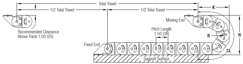
Travel/2 + CL (+ Offset Distance From Center*) = Length
Dynatect recommends mounting the stationary end of the carrier at the center of travel, minimizing the required length.
In cases where center mounting is not possible, add the distance offset from center to the carrier length calculation.
| Height |
R (bend radius) |
H (curve height) |
K (depot) |
CL (curve length) |
| 4 |
1.25 |
4.00 |
3.41 |
6.69 |
| 5 |
1.75 |
5.00 |
4.00 |
9.00 |
| 10 |
4.25 |
10.00 |
6.50 |
16.50 |
Specifications are listed as inches unless otherwise noted
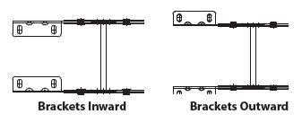
Mounting Brackets
Specify bracket arrangement and direction of flange. Mounting holes can be inward facing or outward facing.
Example: #1 arrangement and inward facing holes = #1-IN
Example: #4 arrangement and outward facing holes = #4-OUT
Standard Mounting Bracket Arrangements

Bracket Flange Mounting Hole Location
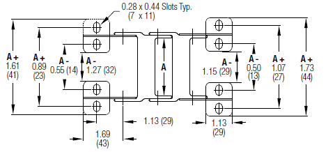
Mounting Bracket Diagram & Dimensions inches (mm)
A = Cavity Width (bar/inside width)
Design Specs - Metric
How To Create A Part Number
P Series:
Model – Height – Length – Bracket (fixed) – Bracket (moving)**
Example: P1-5-36.00-#2OUT-#2IN
PH Series:
Model – Height – Hinged Bar Location* – Length – Bracket (fixed) – Bracket (moving)**
Example: PH2-4-INNER-40.50-#4IN-#4 IN
⇒ Length is specified in inches, to two decimals. It is the distance between flanges
⇒ (see formula on carrier side view diagram)
*Only on PH Series: Hinged bars are available on inner or outer radius. Hinged bars on inside radius is standard. Please specify when ordering.
**Specify bracket flange: inward (IN) or outward (OUT).
Carrier Cross Sectional View
| Model |
A (inside width) |
C (outer width) |
Weight (kg/m) |
| P1 |
32 |
44 |
0.52 |
| PH1* |
32 |
44 |
0.52 |
| P2 |
64 |
75 |
0.61 |
| PH2* |
64 |
75 |
0.61 |
| P3 |
102 |
114 |
0.73 |
| PH3* |
102 |
114 |
0.73 |
*Hinged bars are available on inner or outer radius. Hinged bars on inside radius is standard. Please specify when ordering.
Specifications are listed as millimeters unless otherwise stated
Carrier Side View inches (mm)
Travel/2 + CL (+ Offset Distance From Center*) = Length
Dynatect recommends mounting the stationary end of the carrier at the center of travel, minimizing the required length.
In cases where center mounting is not possible, add the distance offset from center to the carrier length calculation.
| Height |
R (bend radius) |
H (curve height) |
K (depot) |
CL (curve length) |
| 4 |
32 |
102 |
87 |
170 |
| 5 |
44 |
127 |
102 |
229 |
| 10 |
108 |
254 |
165 |
419 |
Specifications are listed as millimeters unless otherwise noted
Mounting Brackets
Specify bracket arrangement and direction of flange. Mounting holes can be inward facing or outward facing.
Example: #1 arrangement and inward facing holes = #1-IN
Example: #4 arrangement and outward facing holes = #4-OUT
Standard Mounting Bracket Arrangements
Bracket Flange Mounting Hole Location
Mounting Bracket Diagram & Dimensions inches (mm)
A = Cavity Width (bar/inside width)